Inside a Solar Hybrid PCU: MPPT Internal Circuitry Explained by its Designer
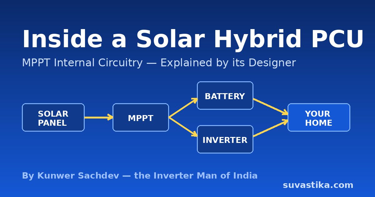
What's really inside a solar hybrid PCU? I have been designing Power Conditioning Units since 2011, when my R&D team built one of India's first integrated solar PCU circuits — an MPPT charge controller, grid charger, pure sine wave inverter, isolation transformer and microcontroller in one box. In this guide I'll walk you through the internal circuitry block by block, with the real test numbers and design decisions behind each stage — not textbook theory.
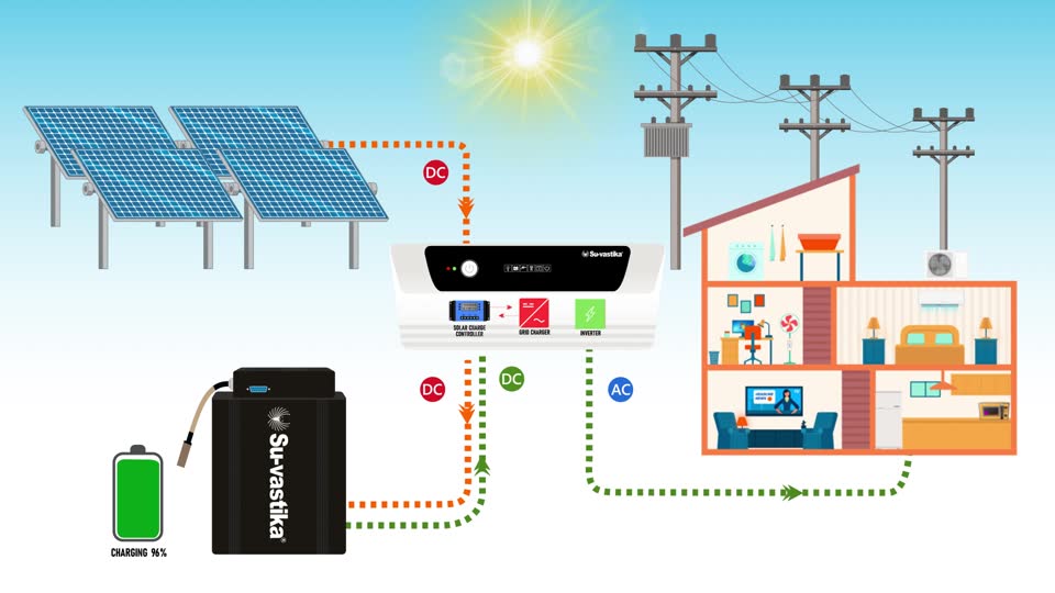
1. Solar Input Stage (PV Array Connection)
Everything starts where the solar panels connect. This stage protects both the unit and the array:
- PV array input terminals — accept the series/parallel string of panels. The string voltage must sit inside the MPPT window — get this wrong and the charge controller suffers (see my guide on matching panel and battery voltages).
- DC disconnect switch — lets a service engineer isolate the array safely.
- Surge Protection Device (SPD) — absorbs voltage spikes from nearby lightning.
- Blocking diode / MOSFET — at night the battery sits at a higher voltage than the dark panels; without this block, current flows backwards into the array. We made reverse-current protection standard after seeing panels mysteriously drain batteries overnight in early field installations.
2. MPPT Charge Controller — We Measured the Difference Ourselves
The MPPT (Maximum Power Point Tracking) controller is a microcontroller-driven DC-DC converter that constantly hunts for the voltage-current point where the panel delivers maximum power. We filed a patent on our microcontroller-based MPPT tracking when we integrated it into the PCU.
Here is something that should have stopped being true years ago but hasn't: PWM charge controllers are still being sold in large numbers across India and Africa, simply because most customers — and many dealers — don't know the difference. The panel industry has evolved from 100W modules to 550–750W, but the awareness hasn't evolved with it. A dealer quotes a lower price, the customer sees "solar charging" on the box, and a third of the generation quietly disappears.
Don't take the "30% better" claim on faith — test it. In our R&D days we benchmarked this on our own rig: from the very same panel, in the same sunlight, the MPPT transferred roughly a third more power to the battery than the PWM. PWM drags the panel away from its maximum power point; MPPT sits on it. On today's 540W and 750W panels that wasted third means 150–250W lost every sunny hour, because these high-voltage panels charging lower-voltage battery banks make the mismatch even bigger. The test method is timeless — same panel, same sunlight, measure the voltage × current actually reaching the battery through each controller. If your dealer cannot show you this measurement, ask why.
3. DC-DC Conversion & the DC Bus
- DC-DC converter — converts the variable MPPT output to a stable DC bus that feeds the inverter and charger.
- Bus capacitors — smooth the ripple on the DC bus.
- Current sensors — in our higher-capacity designs we use Hall-effect sensors on the DC charging path because they measure without breaking the circuit and survive the currents involved.
4. Battery Charging — Solar-Grid Current Sharing
This is the heart of a hybrid PCU and the circuit I am most proud of. The charger doesn't just pick solar or grid — it blends them by current. If the battery's set charging current is 15A and the panels are producing only 10A, the grid contributes exactly the missing 5A. The moment a cloud passes and solar rises, grid draw falls automatically. We called it solar-grid charging current sharing, and it is why a PCU keeps the battery full without burning grid units unnecessarily.
- Charging current follows the C/10 rule: a tubular lead-acid battery takes at most 10% of its Ah capacity — 15A for a 150Ah battery. Exceed it and the electrolyte evaporates, plates harden, and battery life collapses. Lithium batteries accept much faster charging, which is one reason Su-vastika moved to lithium.
- Automatic Temperature Compensation (ATC): a sensor reads ambient temperature and adjusts the charging voltage, because the correct charge voltage of a lead-acid battery shifts with temperature. In our field data this alone extended battery life by around six months.
- Grid charger efficiency: our charger ran at >85% efficiency with 0.85 input power factor at nominal AC input — TUV-verified, not a brochure number.
5. DC-AC Inverter Stage
- Inverter bridge — MOSFETs in smaller models, IGBTs in 2kVA and above, because IGBTs handle high power more robustly. The bridge chops the DC bus into a sine wave under PWM control.
- LC filter — removes switching harmonics, leaving a true sine wave. We insisted on true sine output from the beginning because it extends the life of motors, compressors and electronics.
- Feedback sensors — AC voltage and current sensing keeps output locked at 230V/50Hz as load changes. Our peak inverter efficiency measured 89% in TUV testing.
6. Isolation Transformer — Why We Kept It When Others Dropped It
Many manufacturers delete the isolation transformer to save cost and weight. We kept galvanic isolation deliberately: it separates the electronics from your appliances, kills ground loops, protects against shock, and makes the product far more forgiving of grid abuse — spikes, surges, lightning-induced transients. In our 3-phase machines (up to 500kVA today), a Y/Y transformer also gives clean neutral formation for unbalanced loads. Reliability was the whole brand promise, and the transformer is a big part of it.
7. Change-Over Section & Source Switching
Relay-based change-over connects or disconnects the grid (or a generator) and routes power according to the selected priority mode. The two modes we defined in 2013 are still the industry vocabulary:
- SMB (Solar-Mains-Battery): solar first, then mains when the battery falls below nominal; battery is only discharged to cut-off if mains is absent. For users who want maximum backup reserve.
- SBM (Solar-Battery-Mains): solar first, then battery down to the low-battery pre-warning, and only then mains. For users who want minimum electricity bills.
8. The Microcontroller — Where the Real Engineering Lives
One microcontroller runs everything: the MPPT algorithm, the PWM channels that generate the sine wave and charging waveform, every protection trip, the priority logic and all communication. Our first PCUs ran on a 16-bit microprocessor; today's controllers carry 2–4 UART ports for communication and spare capacity so features can be added by firmware update — we shipped OTA-upgradable behaviour years before it became a buzzword.
The protection logic is where field experience shows. Example: thermal protection doesn't just trip — it hysteresis-cycles. Charging stops when the heat sink crosses 90°C and resumes only after it cools to 70°C, so the unit never sits oscillating at the limit. In the thermal chamber we logged every component — transformer, DC capacitors, heat sinks — across a full day at full load before releasing a design; our 30kVA 3-phase machine held its heat sinks at ~80°C through an 8-hour full-load soak with measured 84.28% AC-to-AC efficiency.
9. Display, Datalogging & Connectivity — From RS-232 to Bluetooth
People think app monitoring is new. Our 2013 PCU already had a true energy meter on board (inverter output V, I, VA, kWh; solar generation kWh, V, I; battery voltage and charge/discharge current), a real-time clock, and one week of onboard datalogging at 1-hour intervals retrievable over an RS-232 port. From there we went to GSM-based remote monitoring (NMS), then Wi-Fi, and today a UART-connected Bluetooth/Wi-Fi dongle streams the same data to a phone app. The sensing architecture barely changed — three-phase machines monitor input/output voltages and currents on all phases, DC bus voltage, Hall-effect charging current, PV voltage/current and heat-sink temperatures — only the last mile got friendlier.
Block-by-Block Summary
| Stage | Key components | The number that matters |
|---|---|---|
| Solar input | SPD, disconnect, blocking diode | String VOC = 1.4–1.8 × battery voltage |
| MPPT controller | µC-driven DC-DC (patent filed) | ~1/3 more power vs PWM — measure it: same panel, same sun, watts at the battery |
| Battery charger | Solar-grid current sharing, ATC | C/10 charging; >85% charger efficiency (TUV) |
| Inverter bridge | IGBT (≥2kVA) / MOSFET + LC filter | 89% peak inverter efficiency (TUV) |
| Isolation transformer | Galvanic isolation, Y/Y in 3-phase | 84.28% AC-AC measured on 30kVA 3-phase |
| Control & protection | MCU, PWM, thermal hysteresis | Stop at 90°C, resume at 70°C |
| Monitoring | Energy meter, RTC, UART → BT/Wi-Fi | 7-day onboard datalog @ 1-hr interval since 2013 |
What Separates a Good PCU from a Cheap One
After putting lakhs of units into Indian homes, my checklist is short: does it have an isolation transformer (most cheap units don't), is the MPPT real (ask for the tracking efficiency, not the marketing percentage), is it IEC/BIS test-reported (our models carried IEC reports per MNRE guidelines from 100VA to 6.25kVA; Su-vastika's range is BIS certified today), and was it thermally validated at full load for hours, not minutes. India's storage-based solar wave is real — pv magazine India covers how these systems are replacing diesel generators — and build quality decides which units survive it.
Frequently Asked Questions
Q. Is PWM still sold? Should I ever buy it?
Yes, PWM still sells widely in India and Africa — purely on price and lack of awareness. With today's high-voltage 550–750W panels it wastes a large share of your generation. Test it the way we did in R&D: same panel, same sunlight, measure the watts reaching the battery through each controller — on our rig the MPPT delivered roughly a third more power.
Q. Why do some PCUs have an isolation transformer and others don't?
Cost. Transformerless units are cheaper and lighter, but lose galvanic isolation — less protection from ground loops, shock and grid transients. We kept the transformer because reliability in Indian grid conditions was the design priority.
Q. What is the difference between SMB and SBM modes?
SMB (Solar-Mains-Battery) uses mains before discharging the battery deeply — maximum backup reserve. SBM (Solar-Battery-Mains) runs the battery down to pre-warning before touching mains — minimum electricity bill. Good PCUs let you choose.
Q. Can I monitor a solar PCU on my phone?
Yes — today over a Bluetooth/Wi-Fi dongle on the MCU's UART port. The underlying energy metering and datalogging have been inside these machines since 2013; only the interface changed from RS-232 cable to a phone app.
Looking for a solar hybrid PCU engineered in India?
Su-vastika builds BIS-certified MPPT solar hybrid PCUs with isolation transformers, lithium-ready charging and app monitoring.
Explore Products Talk to an ExpertRelated guides
From Kunwer Sachdev’s Network
Want to compare prices before you buy?
India’s independent price-comparison and buying-intelligence hub for inverters, batteries and solar — zero affiliate bias.
➤ Compare inverter & UPS prices
➤ Lithium vs lead-acid — full guide
➤ Free backup calculator (lab-tested data)
The story of Kunwer Sachdev — 76+ patents, India’s first plastic-body inverter, and the journey that brought solar into millions of homes.
➤ Pioneer timeline of firsts
➤ Video library — the work in his own voice
Disclaimer: This article is written by Kunwer Sachdev, mentor of Su-vastika. Kunwer Sachdev is no longer associated with Su-Kam Power Systems Ltd. in any capacity. Anyone dealing with Su-Kam should be aware that Kunwer Sachdev has no association with the Su-Kam brand or company.
Part of the Series
Solar PCU & MPPT Charge Controllers: Complete GuideExplore Products
Su-vastika Solar PCU
25+ patents · Made in India · 10,000+ installations