The Importance of Test Parameters for Inverter/UPS Transformers

Inverter/UPS Transformers: Evaluating the Test Parameters of Copper and Aluminium
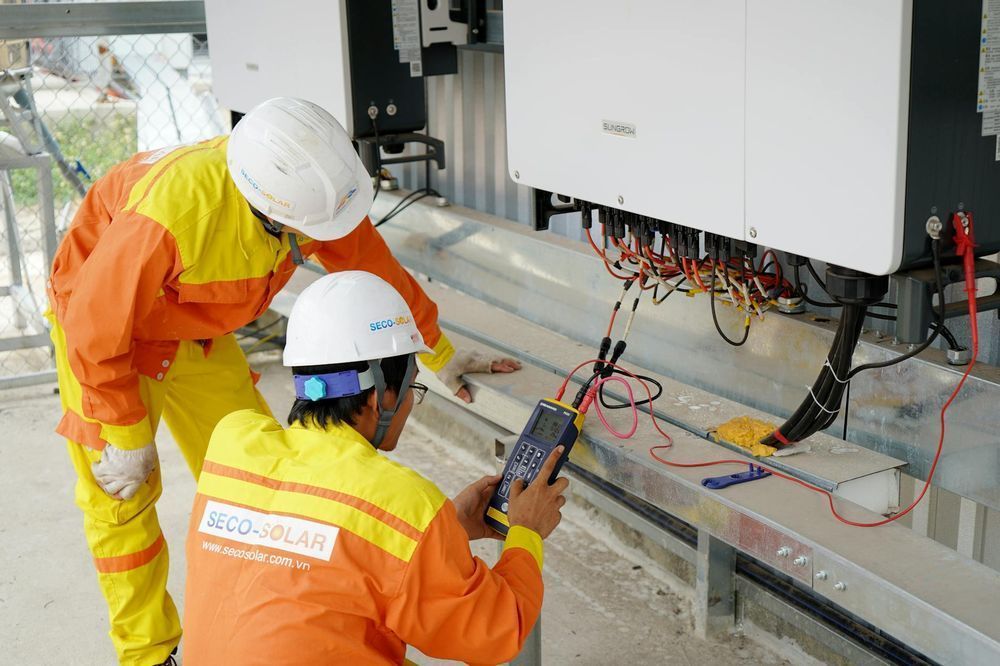
We are comparing a hybrid aluminium and a pure copper transformer for use in a pure sinewave inverter/UPS manufacturing at Su-vastika. Testing the transformer’s parameters is essential to decide whether these parameters are better when we design these two types of transformers. We create a Hybrid transformer where Copper and Aluminum are mixed windings, and the transformers are designed according to the circuit design and software parameters of any Inverter/UPS/ESS, etc.
Another essential safety device we added to our transformers is the automatic thermal sensor cut-off. This thermal sensor removes the transformer from the inverter circuitry if the temperature exceeds the set limits. It is restarted once the temperature is received. The user will not even know if there was any power break.
Users often have a misconception about the choice between copper and aluminium transformers. At Su-vastika, we aim to educate our audience by differentiating these two transformers in this article. The selection of the transformer is based on the duty cycle set for any inverter/UPS design in the microprocessor of that particular software. The primary concern is understanding the transformer specifications required to check the transformer capability. The next step involves a thermal test on a given load for the maximum time. If these parameters are all met, the transformer is deemed suitable for production.
The Importance of Test Parameters for Inverter/UPS Transformers
The Importance of Test Parameters for Inverter/UPS Transformers
Here’s a breakdown of the key points:
- Transformer types: So first, we have to select the model for which the transformer needs to be tested
- Application: These transformers are intended for a pure sinewave inverter.
- Testing parameters: You measured several critical electrical properties of the transformers, including:
- Primary Voltage:
In transformer testing, the primary voltage refers to the voltage applied to the transformer’s primary winding during the test. This voltage is typically not the same as the transformer’s rated voltage but rather a controlled value used to evaluate different aspects of the transformer’s performance.
Here’s a breakdown of the primary voltage’s role in transformer testing:
-
Varied Voltage: The primary voltage can be adjusted during testing to assess the transformer’s behaviour under different load conditions. This helps identify any potential weaknesses or limitations in its operation.
-
Specific Tests: The particular value of the primary voltage applied depends on the type of test being conducted. Here are some common examples:
- Ratio and Polarity Tests: In these tests, a controlled voltage is applied to the primary winding to measure the accuracy of the voltage transformation ratio between the primary and secondary windings and verify the polarity of the output voltage.
- Excitation Current Test: This test measures the current drawn by the transformer’s primary winding when a low voltage is applied to excite the core. This helps assess the efficiency of the transformer’s magnetic circuit.
-
- Secondary Voltage: In a transformer designed for an inverter that converts between 12VDC and 220VAC, the secondary voltage plays two critical roles depending on the mode of operation (inverting or charging):
1. Inverting 12VDC to 220VAC:
- Voltage Step-Up: In this mode, the primary role of the secondary voltage is to be the increased AC output voltage. The transformer acts as a step-up transformer, where the number of turns in the secondary coil is significantly higher than the primary coil. This fulfils the inverter’s function of raising the 12VDC input to the desired 220VAC output.
2. Charging: Converting 220VAC to 12VDC:
- Intermediate Stage: The transformer’s role is less straightforward during charging. The 220VAC input first passes through a rectifier circuit within the inverter that converts the AC voltage to a pulsating DC voltage.
- Voltage Matching: In this stage, the transformer’s secondary voltage is supportive. It might not directly provide the final 12VDC output, but it could be used to:
- Step-Down the Voltage: If the rectified DC voltage is still significantly higher than 12V, the transformer with a lower secondary to primary voltage ratio (acting as a step-down transformer) could further reduce the voltage before it reaches the final regulation stage.
- Isolation: This isolates the high-voltage AC input from the lower-voltage DC output, improving safety and reducing electrical noise.
- Turn ratio: Ratio of turns in the primary and secondary windings, which affects voltage conversion. To achieve the designed secondary voltage, we rely on the concept of turn ratio. This is the ratio between the number of turns in the primary coil (winding) and the number of turns in the secondary coil. By adjusting this ratio, we can control the output voltage according to the formula: Vs/Vp = Ns/Np (Vs = secondary voltage, Vp = primary voltage, Ns = number of turns in secondary coil, Np = number of turns in primary coil).
- Primary No-load currents: Current drawn by the transformer when no load is connected (important for efficiency).
The primary no-load current in a transformer designed for an inverter plays a crucial role, even though the inverter operates by converting DC to AC and vice versa. Here’s why:
No-Load Current Explained:
- When the inverter is not supplying any power to a load (no-load condition), the transformer’s primary winding still draws a small current. This no-load current (I₀) is essential for establishing the magnetic field within the transformer’s core.
- The no-load current has two components:
- Magnetizing current (Im): This reactive component creates the magnetic field. It’s in phase with the applied voltage and doesn’t do any real work.
- Core loss current (Iw): This represents the power wasted due to the core material’s hysteresis and eddy current losses. It’s in phase with the voltage.
Impact on Inverter Transformer:
- Efficiency: The no-load current contributes to power loss in the transformer, even when there’s no load on the inverter. This reduces the overall efficiency of the system. In inverter applications, where efficiency is critical, minimising the no-load current is desirable.
- Transformer Design: Manufacturers consider the inverter’s operating cycles and target efficiency when designing the transformer. Techniques to reduce no-load current include:
- High-quality core materials: Lower hysteresis and eddy current losses can significantly reduce the core loss current (Iw).
- Optimized design: Optimizing the core geometry and winding configuration can help reduce the magnetising current (Im).
Inverter Operation:
- While the no-load current is significant during standby or no-load conditions, the inverter’s primary function revolves around power conversion.
- 12VDC to 220VAC (Boost Mode): In this mode, the inverter uses a switching circuit to control the primary current, creating a pulsating magnetic field that induces a much higher voltage (220V AC) in the secondary winding.
- 220VAC to 12VDC (Buck Mode): The inverter operates buck mode during charging. It controls the primary current to draw power from the 220V AC input and converts it to a regulated 12V DC output through rectification and filtering.
- Secondary No Load Current:
-
Transformer Losses: Even within the inverter circuit, the transformer will experience core and copper losses when operating. These losses contribute to a small current draw on the 12V input side (in inverter mode) to compensate for this energy dissipation.
-
Transformer Efficiency: The efficiency of the transformer plays a crucial role in the overall efficiency of the inverter. The transformer’s lower no-load current (and core losses) translates to less wasted power and higher overall inverter efficiency.
In conclusion, while the concept of a no-load current on the secondary side of a traditional transformer doesn’t directly apply to inverters, transformer losses within the inverter circuit still influence the overall power consumption.
-
- Output Voltage Sense: The output voltage sense circuit monitors the voltage at the inverter’s output (12VDC or 220VAC depending on the mode). This information is fed back to the inverter’s control unit called Microprocessor of the Inverter.
Regulation:
The control unit uses the sensed output voltage to regulate the inverter’s operation and ensure it delivers the desired output voltage. This is particularly important because inverters typically use a technique called Pulse Width Modulation (PWM) to generate the AC voltage. By adjusting the duty cycle (on vs off time) of the PWM signal, the control unit can fine-tune the average voltage delivered to the output.
Benefits:
Output voltage sense offers several benefits:
- Accuracy: It helps maintain a consistent and accurate output voltage, even under load variations. This is essential for powering sensitive electronics that require a stable voltage supply.
- Protection: By monitoring the output voltage, the control unit can detect potential overvoltage or undervoltage conditions. It can then take corrective actions, such as shutting down the inverter or limiting the output power, to prevent damage to the inverter or connected equipment.
- Efficiency: Regulation based on actual output voltage allows the inverter to optimize its operation for efficiency.
- Primary Winding resistances: The primary and secondary windings’ resistance affects power loss.
Role of Primary Resistance:
- Power Loss: The primary resistance creates a loss of power in the form of heat. This reduces the overall efficiency of the inverter during both boost (12V to 220V) and buck (220V to 12V) operations.
- Circuit Design: The designer balances the primary resistance with other factors like core losses and desired output current to achieve optimal efficiency for the inverter’s intended use.
Factors Affecting Primary Resistance:
- Wire Gauge: The thickness of the wire used for the primary winding plays a crucial role. Thicker wires (lower gauge numbers) have lower resistance but also come with limitations like increased size and cost.
- Number of Turns: While the turns ratio (primary to secondary) determines the voltage conversion, the total number of turns in the primary winding also affects resistance. Generally, a higher number of turns leads to higher resistance.
- Operating Frequency: Inverters typically operate at higher frequencies compared to power transformers. This can necessitate using special wire types or construction techniques to minimize skin effects and proximity effects, which can increase resistance at high frequencies.
- Secondary Winding resistance:
In a transformer designed for an inverter that converts 12V DC to 220V AC (and vice versa for charging), the secondary winding resistance plays a crucial role, but it doesn’t directly control the voltage conversion. Here’s a breakdown:
Functionality in Voltage Conversion:
-
Not the Main Factor: Unlike the turn ratio, which is the primary determinant of voltage conversion in a transformer, the secondary winding resistance itself doesn’t directly control the output voltage.
-
Power Loss: The secondary winding resistance does, however, contribute to power loss in the transformer. This happens because the current flowing through the winding encounters resistance, dissipating some energy as heat. This can lead to a slight reduction in the available output voltage at the secondary terminals compared to the ideal voltage based on the turn ratio.
Importance of Low Resistance:
-
Efficiency: For an inverter transformer, minimizing power loss is crucial for efficiency. Therefore, manufacturers aim for a low secondary winding resistance. This helps ensure that most of the input power is transferred to the output with minimal energy wasted as heat.
-
Wire Gauge and Material: To achieve low resistance, the secondary winding is typically made with thick wires of a material with high conductivity, such as copper. Thicker wires provide a larger cross-sectional area for current flow, reducing resistance.
-
- Primary Winding inductances:
Role of Primary Inductance:
-
Energy Storage: The primary inductance acts as a temporary storage unit for energy. When the inverter switches the DC on and off in the primary winding, the inductance resists the sudden change and helps maintain current flow. This is crucial for generating a smooth and efficient AC output on the secondary side.
-
Resonant Frequency: The primary inductance, along with the primary winding capacitance, creates a resonant frequency in the inverter circuit. This resonant frequency should ideally match the switching frequency of the inverter for optimal power transfer and efficiency.
-
- Secondary Winding Resistance: The secondary winding resistance (Rs) is an important parameter in any transformer, including inverter transformers. It represents the opposition to current flow within the secondary winding itself. While Rs is crucial for understanding the transformer’s efficiency and power loss, it plays a slightly different role in inverter transformers compared to standard power transformers.
Here’s a breakdown for inverter transformers in bi-directional DC-AC and AC-DC conversion (12V to 220V and vice-versa):
Impact on Operation:
- Power Loss: Higher Rs translates to higher energy dissipation as heat in the secondary winding, reducing overall efficiency during both voltage conversions (12V to 220V and 220V to 12V).
- Voltage Regulation: Rs affects the output voltage at the secondary winding. When a load is applied (during charging for example), the current through the winding increases. This increase in current leads to a voltage drop due to Rs. Minimizing Rs helps maintain a more stable output voltage.
- Primary Winding Inductance: the primary inductance plays a significant role in the inverter’s function:
The inductance can vary slightly depending on whether the transformer is operating in boost mode (12V to 220V) or buck mode (220V to 12V).- Limits Current Surge: Inductance opposes any change in current. In the inverter, it helps limit the initial surge of current when switching from DC to AC or vice versa.
- Energy Transfer: Along with the turn ratio and core material, inductance affects the efficiency of energy transfer between the input and output.
- Secondary Winding Inductance: The secondary winding inductance (Ls) in a bi-directional inverter transformer plays a crucial role in its operation during both DC-AC (boosting) and AC-DC (buckling) conversions. Here’s how it impacts the process:
DC-AC (Boosting 12V DC to 220V AC):
- Ls opposes rapid changes in current: When the inverter switches on, Ls tries to resist the sudden rise in current through the secondary winding. This helps to control the rate of current rise and prevents current spikes.
- Inductive energy storage and release: During the on-time of the inverter switch, energy is stored in the magnetic field created by Ls. When the switch turns off, this stored energy is released back into the circuit, contributing to the output voltage on the secondary side.
AC-DC (Buckling 220V AC to 12V DC):
- Ls smooths out the rectified AC waveform: During rectification of the incoming AC voltage, Ls helps to smooth out the pulsating DC output from the rectifier diodes. This is because Ls opposes the rapid changes in current, resulting in a more continuous flow of current.
- Phase neutral sequence:
- The inverter section takes the 12V DC and converts it to a high-frequency AC waveform.
- This high-frequency AC is then passed through a transformer to step up the voltage to 220V AC.
- In this process, the inverter creates a three-phase or single-phase AC output depending on the design.
-
Neutral on the AC side:
- Depending on the inverter transformer design and the AC system it connects to, there might be a neutral connection on the 220V AC side.
- In some cases, the inverter transformer might have an isolated neutral, meaning there’s no direct connection between the neutral point and ground.
- Power loss: In an inverter transformer with bi-directional technology (converts 12V DC to 220V AC and vice versa), power loss is inevitable during both conversion processes. Here’s a breakdown of the two main types of losses:
1. Inverter Losses:
- Conduction Losses: These occur due to the resistance of internal components like switches (transistors) and windings. As current flows through these components, some energy is dissipated as heat.
- Switching Losses: When the inverter switches on and off to convert DC to AC, there’s a momentary surge in current and voltage. This rapid switching creates some energy loss.
2. Transformer Losses:
- Iron Losses: These stem from the properties of the transformer core material. They include:
- Hysteresis Loss: When the magnetic field in the core reverses direction (during AC to DC conversion), some energy is lost due to internal friction within the material.
- Eddy Current Loss: The changing magnetic field induces circulating currents within the core, which dissipate as heat.
- Primary Voltage:
The Importance of Test Parameters for Inverter/UPS Transformers
-
Testing parameter
The Importance of Test Parameters for Inverter/UPS Transformers
By comparing these values, you can assess each transformer type’s performance and determine which is better suited for the pure sinewave inverter application. This testing equipment were developed under the guidance of Mr. kunwwer Sachdev founder Su-kam known as Inverter Man of India.
Disclaimer: It is important to note that while Mr. Kunwer Sachdev founded Su-Kam Power Systems, he is no longer associated with the company as of 2019. Any information regarding his involvement in the company's operations, strategies, or future plans reflects his tenure prior to that date. Therefore, any discussions or analyses of Su-Kam Power Systems should be considered in the context of his past contributions and not his current association with the company. He currently mentors Su-vastika.
Found this story worth sharing? Post it to your network — it takes one click:
About the Author
Kunwer Sachdev — known as the Inverter Man of India and the Solar Man of India. Founder of Su-Kam, holder of 106 technology filings, and mentor to Su-vastika. Read his story →
Follow on LinkedIn · kunwersachdev.com
Kunwer Sachdev exited Su-Kam in 2019 and is not responsible for any activity of the company since. Full disclaimer →
Part of the Series
Solar PCU & MPPT Charge Controllers: Complete GuideExplore Products
Su-vastika Solar PCU
25+ patents · Made in India · 10,000+ installations